
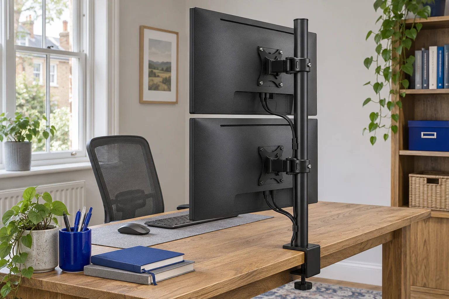
The fit comparison
Compare the published fit limits
Check both screens individually, then compare the required mounting-centre positions. Pole length and screen diagonal alone do not establish that a pair will stack.
Scroll across the table for every fit check.
| Mount | Screens | Per screen | Pole / height | Mounting |
|---|---|---|---|---|
| Duronic DM35V2X1 A compact two-screen stack | 13–27″ each | Up to 8 kg each | 80 cm pole; usable centres must be confirmed | Clamp included; grommet kit separate |
| VIVO STAND-V002R A wider-screen stack to measure | 13–34″ each | Up to 22 lb (about 10 kg) each | About 80 cm pole; centre range not published | Clamp or included grommet |
Measure the casings and mounting-hole centres
A vertical stack can free the sides of a narrow desk, but it adds a second fitting question: where must each mounting head sit? Two screens can meet the individual weight limits and still need centre positions the mount cannot provide.
Start with six dimensions. Record the full casing height of each display, each bottom-edge-to-VESA-centre offset, the lower screen's clearance above the desk and the gap between the casings. Use centimetres throughout. For a 180 mm offset, enter 18 cm.
The VESA centre is the centre of the mounting-hole pattern, not the outside edge of an adapter or mounting plate. Measure in the orientation you plan to use. A screen's diagonal describes its image size; it does not provide the casing height or the position of those holes.
Follow the dimensions from the desktop upwards

In this example, the lower centre is 8 + 18 = 26 cm above the desk. The lower casing ends at 44 cm; the 2 cm gap puts the upper casing's bottom at 46 cm. Add its 18 cm offset and the upper mounting centre reaches 64 cm. The upper casing extends another 18 cm above that centre, reaching 82 cm overall.
Keep those last two figures distinct. A stack top at 82 cm does not mean an 82 cm pole is required: the head supports the VESA centre below the casing's top edge. Equally, an 80 cm pole does not promise an 80 cm usable head position. Collars, joins, head dimensions and end clearances affect the positions available.
Calculate your two mounting heights
Plan both mounting positions
Stacked-monitor height calculator
Enter all measurements in centimetres, using the full casings and the VESA offsets in the planned orientation. The example starts with two 36 cm-high casings, centred mounting holes, 8 cm above the desk and a 2 cm gap.
- Lower VESA centre above desk
- 26 cm
- Upper VESA centre above desk
- 64 cm
- VESA-centre separation
- 38 cm
- Top of stack above desk
- 82 cm
Lower centre: 8 + 18 = 26 cm. Upper centre: 8 + 36 + 2 + 18 = 64 cm. Separation: 64 − 26 = 38 cm. Stack top: 8 + 36 + 2 + 36 = 82 cm.
A zero gap makes the casings meet in this flat layout. Check the required space for tilt, movement and ventilation before choosing a gap.
Results describe an untilted front view and are rounded to 0.1 cm. Compare both centre heights and their separation with the mount's confirmed usable positions. Check screen loads, tilt, casing depth, cables, fixing and viewing position separately.
Six setups with different fitting consequences
These examples use illustrative casing dimensions and mounting offsets. They show how changing one part of the arrangement affects the centres or overall height. All figures are in centimetres. The casing/offset pairs below mean full casing height / distance from its bottom edge to the VESA centre.
Scroll across on a small screen. Use “Load this example” to reproduce a row in the calculator above.
| Example inputs | Lower centre | Upper centre | Centre separation | Stack top |
|---|---|---|---|---|
| Equal casings, centred holesLower casing/offset: 36 / 18 cm Upper casing/offset: 36 / 18 cm Lower clearance: 8 cm · Gap: 2 cm | 26 cm | 64 cm | 38 cm | 82 cm |
| Same casings, off-centre holesLower casing/offset: 36 / 24 cm Upper casing/offset: 36 / 12 cm Lower clearance: 8 cm · Gap: 2 cm | 32 cm | 58 cm | 26 cm | 82 cm |
| Different casing heightsLower casing/offset: 32 / 16 cm Upper casing/offset: 44 / 22 cm Lower clearance: 8 cm · Gap: 2 cm | 24 cm | 64 cm | 40 cm | 86 cm |
| A larger gap between screensLower casing/offset: 36 / 18 cm Upper casing/offset: 36 / 18 cm Lower clearance: 8 cm · Gap: 6 cm | 26 cm | 68 cm | 42 cm | 86 cm |
| Raise the whole stack by 4 cmLower casing/offset: 36 / 18 cm Upper casing/offset: 36 / 18 cm Lower clearance: 12 cm · Gap: 2 cm | 30 cm | 68 cm | 38 cm | 86 cm |
| A tall upper casingLower casing/offset: 36 / 18 cm Upper casing/offset: 60 / 30 cm Lower clearance: 8 cm · Gap: 2 cm | 26 cm | 76 cm | 50 cm | 106 cm |
Same stack height, different head positions
The first two rows have the same casing heights, clearance and gap. Both reach 82 cm above the desk. Moving the lower VESA offset from 18 to 24 cm raises its required centre from 26 to 32 cm. Moving the upper offset from 18 to 12 cm lowers that centre from 64 to 58 cm. The required centre separation falls from 38 to 26 cm.
That 12 cm change happens without altering the space occupied by the casings. It is why a shared monitor diagonal, or even a shared casing height, cannot establish the spacing between mounting heads. Check the smallest head spacing the mount can actually provide as well as its highest usable position.
Raising the lower screen moves both centres
Increasing the lower clearance from 8 to 12 cm adds 4 cm to both mounting-centre heights and the top of the stack. The separation remains 38 cm. The larger-gap example also raises the upper centre to 68 cm, but its lower centre stays at 26 cm and the separation becomes 42 cm.
The same upper-centre result can therefore describe different lower-screen positions. Compare all four outputs, and keep your keyboard, lower-screen viewing position and the space above the upper casing in the plan.
A taller upper screen affects the whole envelope
The tall-upper-casing row needs an upper centre at 76 cm, while its top reaches 106 cm. Those inputs describe a much taller assembly even though the lower centre is unchanged. For a portrait display, use its actual casing and hole-pattern dimensions in that orientation; do not simply reuse its landscape VESA offset.
The formulas behind the results
Lower VESA centre = lower clearance + lower bottom-to-VESA offset.
Upper VESA centre = lower clearance + lower casing height + casing gap + upper bottom-to-VESA offset.
Centre separation = upper VESA centre − lower VESA centre.
Top of stack = lower clearance + lower casing height + casing gap + upper casing height.
All output heights use the desktop surface as their starting point. If a mount drawing measures from the top of a clamp housing, or describes a different reference point, reconcile that difference before comparing figures. Pole length alone leaves that reference-point question unanswered.
The calculation treats the casings as level rectangles in a front view. Tilting either display changes how its corners and depth relate to the other screen. Curved housings, rear connectors, adapters and moving joints need space beyond the six entered dimensions. An offset that falls outside its casing height is rejected, as are missing, negative or non-numeric measurements. Zero casing gap is accepted as a drawing boundary and clearly flagged for a separate movement and ventilation check.
Compare two mounts after calculating the centres
Duronic DM35V2X1: a smaller-screen vertical stack
The selected Duronic lists 13–27 inches and up to 8 kg per screen, with VESA 75 × 75 or 100 × 100 mm. Its 80 cm pole and two short arms provide the structure for a vertical pair. Compare your calculated centre positions with the actual heads and collars; the pole's end is not a guaranteed mounting-centre position.
The manufacturer gives a 5–68 mm clamp range and identifies the DM-GR-01 as a separate grommet option. Check the desktop material, clamp contact and the kit supplied before choosing the fixing. Its published ±15° tilt range is an adjustment limit, not proof that a tilted upper casing will clear the lower one.
A compact two-screen stack
Duronic DM35V2X1
Two separate mounting heads on a tall pole put compatible screens one above the other. Short arms suit a stack that stays largely in position.
Each screen must meet the 13–27 inch and 8 kg limits. The 80 cm figure is pole height, not a guaranteed screen-centre range. Check casing heights and VESA offsets. The optional DM-GR-01 grommet kit is separate.
- 13–27″ each
- Up to 8 kg each
- VESA 75 × 75 or 100 × 100 mm
VIVO STAND-V002R: a wider published screen range
The VIVO lists 13–34-inch screens and up to 22 lb per monitor, approximately 10 kg. It includes clamp and grommet hardware. The manufacturer's pole figure is 31.5 inches, approximately 80 cm. It does not establish the two usable VESA-centre positions or the minimum space between the heads.
There is a fitting discrepancy worth keeping visible. The current assembly manual shows a 10–88 mm edge-clamp range, while the product page gives a 3.25-inch maximum, approximately 82.6 mm. This guide uses 10–82 mm as the conservative common range for shortlisting and requires matching the supplied version. The manual's through-desk fixing has its own 10–80 mm thickness range and hole requirements; those are separate from the clamp figures.
A wider-screen stack to measure
VIVO STAND-V002R
A tall mechanical pole supports two compatible screens in a vertical layout, with clamp and grommet hardware. It extends the published size range beyond the smaller Duronic stack.
Check both screen loads and VESA-centre positions. The current manual shows 10–88 mm for the clamp, while the product page gives a lower maximum of 3.25 inches (about 82.6 mm). Use the common 10–82 mm range for shortlisting and match the supplied version. Check grommet limits separately.
- 13–34″ each
- Up to 22 lb (about 10 kg) each
- VESA 75 × 75 or 100 × 100 mm
A pair within the VIVO's screen and weight limits still needs the casing, centre-position and desktop checks above. Its wider tilt range also requires more careful corner and cable planning when the upper screen leans towards you.
Check the complete stack and the way you will view it
A shared attachment carries both displays and the mount. Check the furniture's approval for that concentrated loading and the proposed fixing position. A top supporting two monitors on their original stands may have a different load distribution from a pole clamp. See the desktop-material guide and clamp-clearance guide.
Follow the exact mount's assembly and loading sequence. Support each screen before releasing a loaded collar or head, and preserve access to the adjustment fasteners. These are mechanical pole arrangements; the calculator describes their required positions rather than a mechanism for moving loaded screens freely throughout the day.
Compare the upper screen's role with its position
A vertical pair can work well when the lower display carries the main task and the upper display holds occasional reference material. Check whether you can read the upper screen from your normal seated position without repeatedly lifting your chin. HSE's workstation guidance provides a starting point for screen positioning; the calculator does not determine a comfortable viewing angle.
For equally intensive work across both screens, compare a side-by-side dual arm or two independent singles. Keep your normal chair and keyboard positions while planning; changing the chair height solely to reach the upper screen can create a different keyboard or leg-clearance problem.
Leave room for cables, tilt and rotation
Include the upper display's ports, the route down the pole and the nearest sockets. A cable that reaches the lower screen may not reach the upper one with sufficient slack for adjustment. Keep ventilation, power buttons, webcams and the upper casing's full depth accessible.
If either screen rotates, calculate the dimensions in its final orientation and then check the corner sweep through the intended movement. A gap between level front-view rectangles does not establish clearance through a rotation or tilt. The monitor-weight guide helps separate bare-screen weight from shipping and stand figures when comparing each head's load.
Common stacked-monitor questions
Will two 27-inch screens fit on an 80 cm pole?
Diagonal and pole length are not enough to establish fit. Calculate both VESA-centre heights using the full casings, mounting-hole offsets, lower clearance and casing gap. Then check the mount’s usable head positions and minimum head spacing. Screen tops can extend above a pole, so stack-top height and pole length are different measurements.
Can a stacked mount hold different-size monitors?
Possibly, if each screen meets its own load, size and VESA limits and the required mounting positions are available. Enter each casing height and VESA offset separately. Use the dimensions in the planned orientation rather than assuming the holes are centred.
Is the weight rating for both screens combined?
The Duronic’s 8 kg and VIVO’s 22 lb limits here apply to each screen. Include accessories carried by each head. The desktop and fixing must support the complete installation, including the mount and both displays.
What happens if I increase the gap between the screens?
With the lower screen fixed, adding 4 cm to the casing gap raises the upper VESA centre and the stack top by 4 cm. It also increases centre separation by 4 cm. Check the available head position, cable slack and the upper viewing position again.
Does the calculator account for tilted or portrait screens?
It calculates a level, untilted front view. For portrait use, enter the actual casing heights and bottom-to-VESA offsets in that orientation, then check the rotation sweep separately. Tilt, curved casing depth, cables and head hardware need separate clearance checks.
Sources and calculation notes
Product configurations, specifications and fitting documents reviewed in November 2026. The six worked layouts use illustrative casing dimensions and offsets. Their results follow the formulas above; product limits and usable-position checks are separate.
- Duronic DM35V2X1 specifications and fitting sheet — per-screen limits, mechanical mounting arrangement, pole and clamp information.
- VIVO STAND-V002R product specifications and current series assembly manual — screen and load limits, pole figure, included fixings and the distinct clamp/grommet ranges. The product-page and manual clamp maxima differ, as explained above.
- HSE display-screen guidance — workstation positioning. The casing dimensions, VESA offsets and gaps in the examples are chosen inputs, not HSE recommendations.
The product cards link to the selected Amazon UK configurations. Check the actual model, supplied instructions and monitor dimensions before finalising a stack.